Week 10: Output Devices
Assignment:
- Add an output device to a microcontroller board you've designed and program it to do something
This week goal is to fabricate a board adding an output device and program it.
Machines:
- Trotec Speedy 300
- Soldering heat gun
Software:
Components:
- 10 pin LCD connector
- 1 ATtiny 44
- 6 pin ISP connector
- 4 pin power connector
- 1 Xtal Resonator 20 MHz
- 1 Resistor 1K
- 1 Resistor 10K
- 1 Resistor 100K
- 1 IC Regulator 5V
- 1 Capacitor 1uF
As suggested in class to use an otuput device I'll use in my project, I decided to try with an LCD.
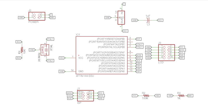
Firs of all I used Neil's board a because I have not so much experience in electronics and I still need to follow steps. I used Eagle to get the schematic and board following Neil's design.
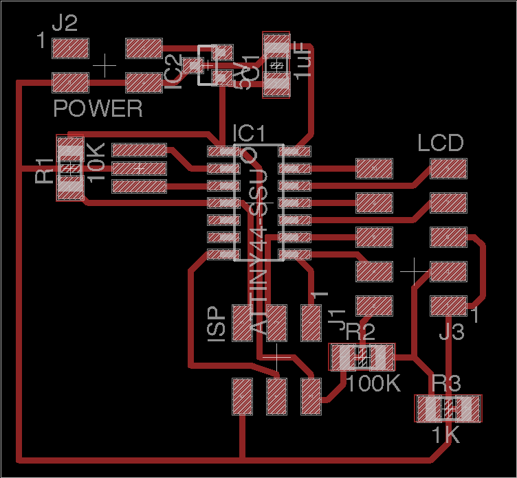
To fabricate and construct my board, I followed the same steps than Assignment 6, using a stencil cut in a Laser Trotec Speedy 300 to paint the traces and etch in ferric perchloride the rest copper areas I didn't need.
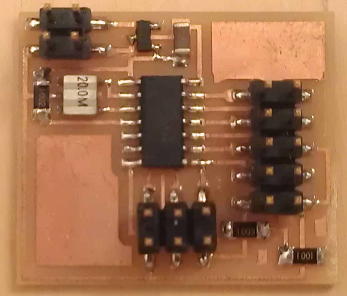
Once finished I start the soldering process using soldering paste and a heat gun, this is my board finished:
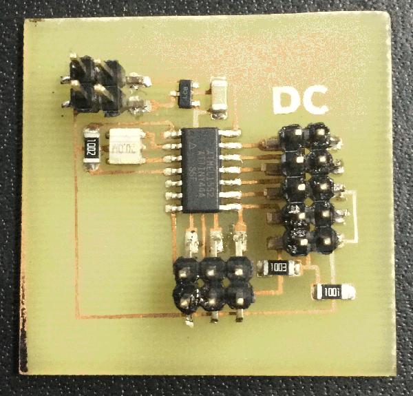
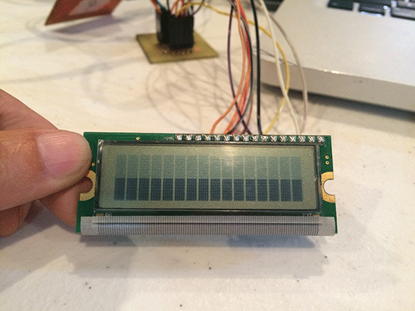
Once I tested everything was right with my board, I start to connect it and test the LCD, I knew everything was rigth because it desplayed the lower row in black when I connected it. For the power supply I use a modifyed 9V cellphone charger.
Doign that I start to program it with Make and using my FabISP board following the next steps:
1. Download Neil's .c and .make files.
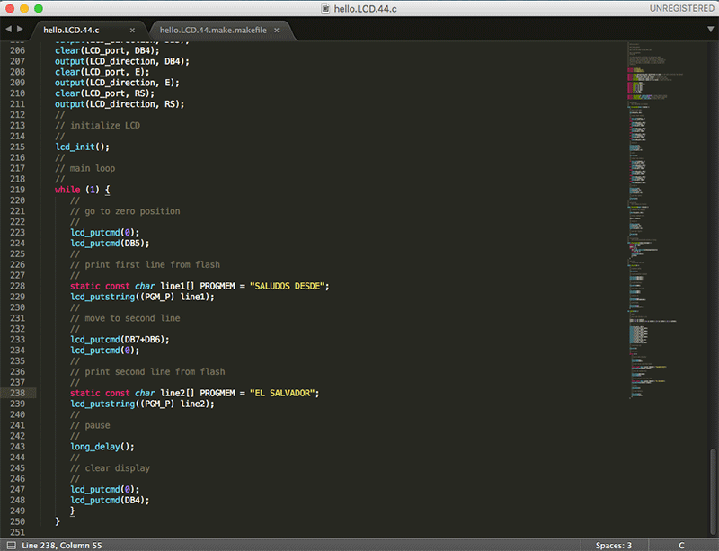
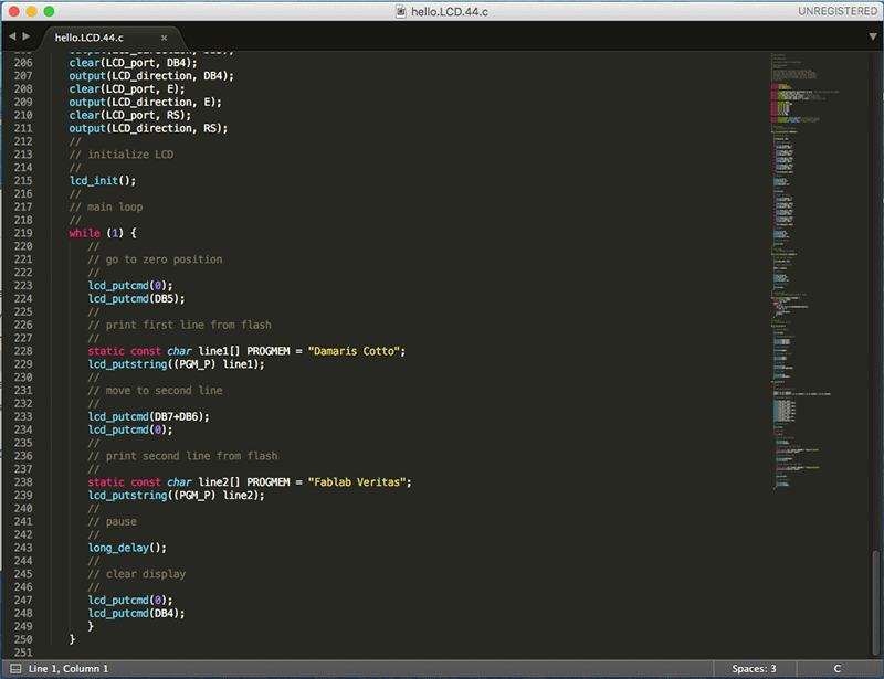
2. I wanted to print different words in the LCD screen than Neil's sample, to do that I used Sublime Text to make changes and save.
3. Open Terminal located in Applications folder and changed directory to the folder where saved the .c and .make files.
4. Command "make -f hello.LCD.44.make.makefile program-usbtiny-fuses" to let the ATtiny 44 know the clock speed and the pins distribution.
5. Command "make -f hello.LCD.44.make.makefile program-usbtiny" to upload the C program.
Doing that, I complied all the C file contents and program the board to print "SALUDOS DESDE EL SALVADOR".
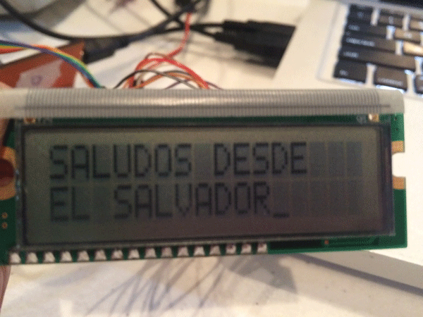
LCD screen video 1 from Damaris Cotto on Vimeo.
I also tried changing the wording in the C file and compling again.
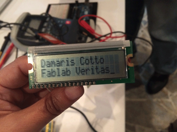
LCD screen video 2 from Damaris Cotto on Vimeo.

